Airbrake 2025
International Rocket Engineering Competition - UVA Rocketry - Sabre II
Purpose
Based on other winning teams’ strategies, it was decided that an airbrake module used to arrest the rocket as it approaches 10,000 feet was a necessary component.
Design
Although we attempted an airbrake subsystem for Spaceport America Cup 2024, this was the first year that a dedicated subteam was allocated to design a module intended for use in competition. The first decisive moment for the airbrake subsystem was choosing an umbrella design, like the airbrake on an F-15 Eagle, or a “petal” design. Advanced teams have found the most success with flaps; however, their subsystems required multiple years to develop. As a result, we opted for the petal design for ease of design and manufacturing with the goal of implementing it into the rocket for competition inside of about 8 months.
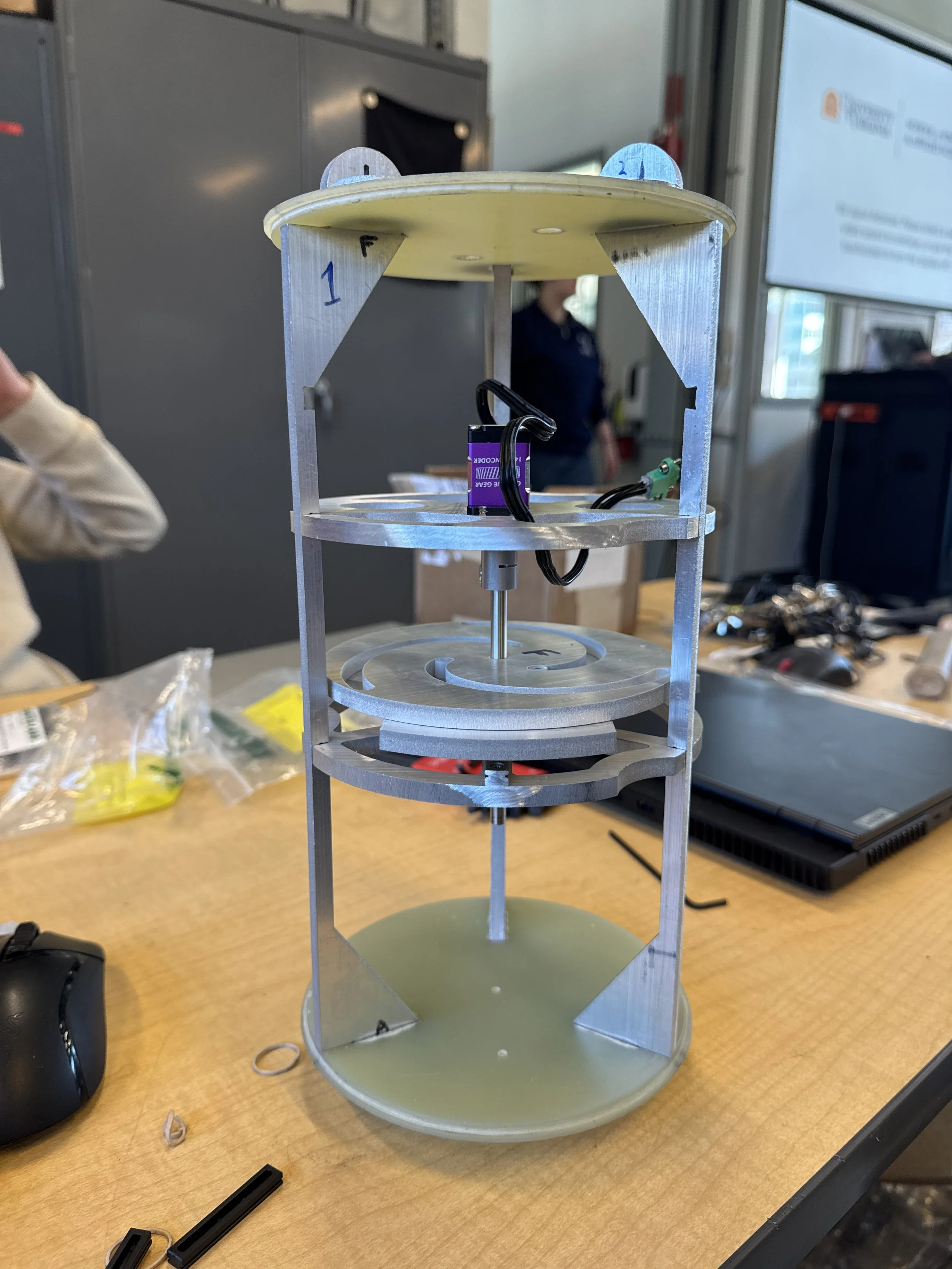
Structure & Materials
The module is composed of three shelves held together by three “stringers”: the baseplate, servo plate, and electronics tray. The baseplate, servo plate, and stringers are composed of 0.25” aluminum, and the electronics tray is 3D-printed from ABS. Aluminum was chosen for the baseplate, servo plate, and stringers because relatively light and strong, and basic FEA revealed that the structure could withstand the forces expected at launch and during flight. The electronics tray only needed to support a PCB and an antenna and didn’t contribute to the structural integrity of the module, so ABS was the chosen material because it’s light and has higher heat resistance than other thermoplastics.
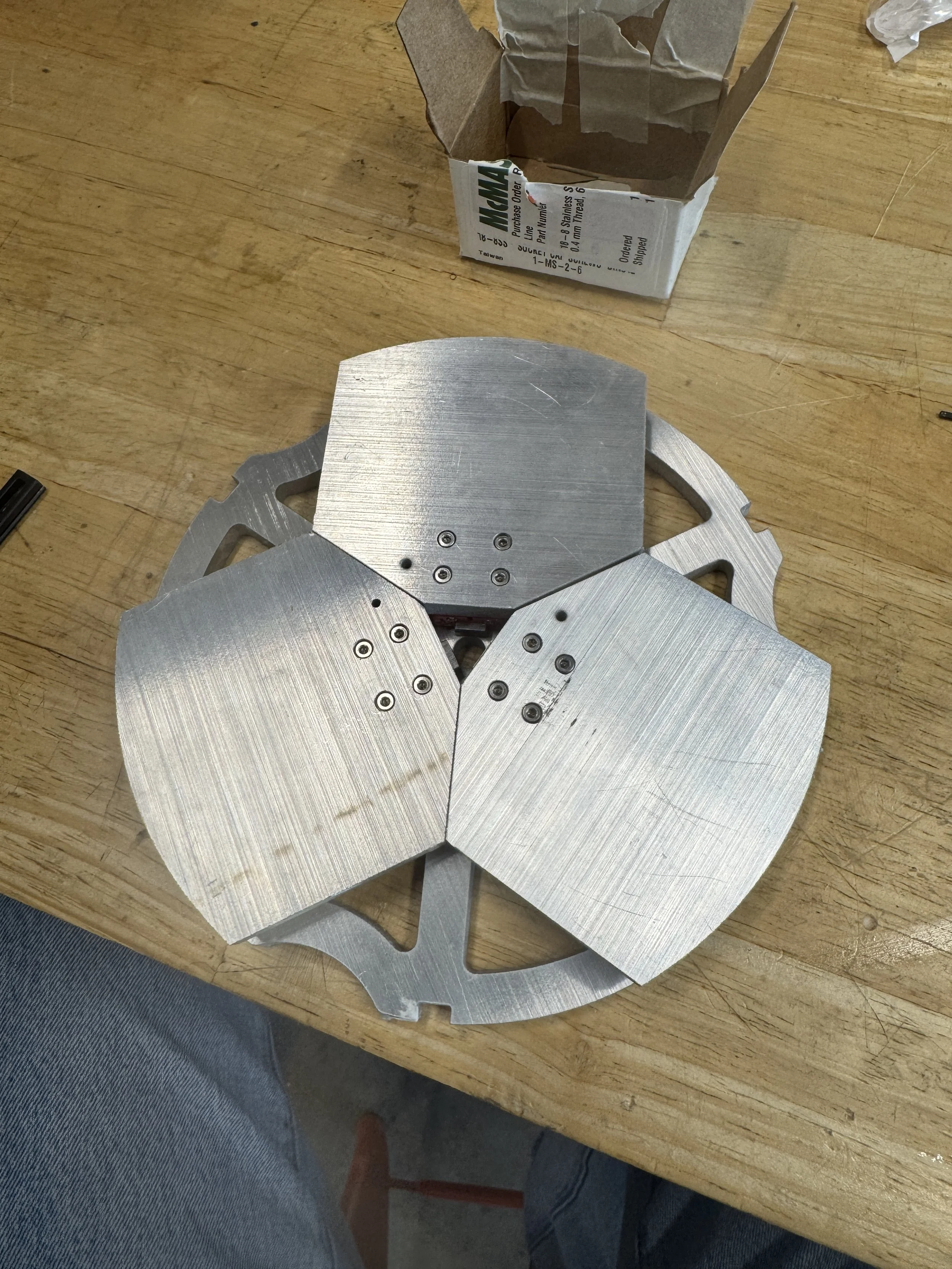
Mechanical System: Petals & Cam
The main mechanical system, the petals and cam, are bound by the baseplate and servo plate. The petals and cam are made from 1/4” aluminum like the baseplate and servo plate. The petals each ride on a ball-bearing carriage connected to a rail, which is screwed into the baseplate. This ensures low-friction translation as the cam is rotated and the petals extend. The petals’ motion is governed by the cam via a steel dowel sleeved by the nylon bearing. These bearings fit snugly inside the slots cut in the cam, which are mathematically defined to establish a linear relationship between angular and translational displacement.
The cam is rotated by a D-shaft which is connected to the servo through an adapter. The shaft extends through the baseplate where it can spin freely and be linked with the retraction mechanism.
Mechanical System: Retraction
One of the guidelines for the use of an airbrake is to have an emergency retraction mechanism in the event of an electrical failure. After much deliberation, we were inspired by garage door opener torsion springs.
The mechanism is essentially composed of a torsion spring and a “winder.” The D-shaft runs through the center of the torsion spring, and the spring is held in place in the vertical axis by the winder and then a collar. The top flange of the torsion spring is fixed at a hard-point on the bottom of the baseplate and the bottom flange is rotated by the winder, creating tension as the cam rotates and extends the petals.
Of course, stripping the servo was a concern, which will be addressed in testing.
Manufacturing
The components of the airbrake which were manufactured were the base plate, cam, servo tray, electronics tray, petals, and struts. All of those components were made from 1/4” aluminum except for the electronics tray, which was 3D-printed from ABS. The aluminum parts were cut using a water jet and then sanded and filed. The water jet required several trials due to the team’s unfamiliarity with its tolerance, but we eventually figured it out. All other components were OTS, some of which being modified (like the coupler tube).
Full subsystem testing began in early March 2025 once the module was fully constructed. This involved basic functionality tests while the system experiences vibrations. Unfortunately, the system was never tested while the rocket was in flight.
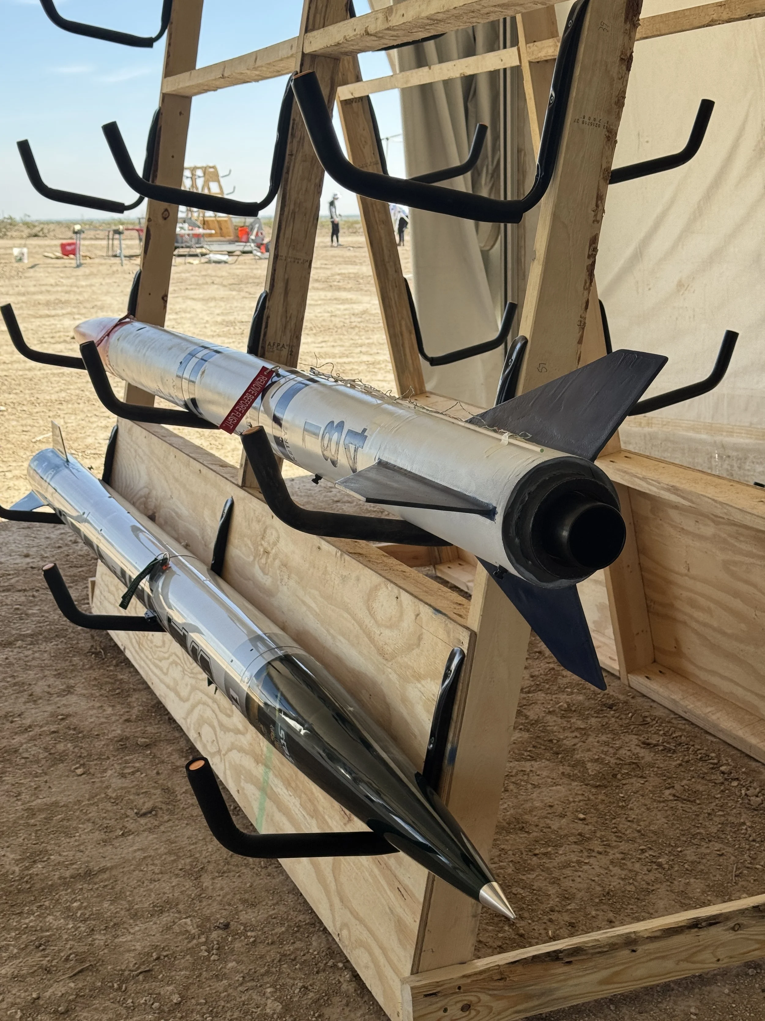
Sabre II performed a sub-scale launch in February, and the software for the system was not complete to monitor effectiveness during flight, so the airbrakes were not used. A full-scale launch was scheduled for March, but it was cancelled due to wildfires in North Carolina, and locating another 10,000’ launch site on short notice was not possible. With the lack of data for the airbrake combined with other systems rolling over their mass-budgets, it was decided to remove the dynamic components of the airbrake for the competition launch at IREC.
Despite the lack of airbrakes, the rocket achieved an altitude of 10,019’, less than 0.2% over the target apogee, securing a first place finish in the 10K COTS category and second place overall at IREC.
Testing